The Number Of Slots Per Pole Should Be
- The Number Of Slots Per Pole Should Beams
- For A 5 Kw Dc Motor The Number Of Slots Per Pole Should Be
- The Number Of Slots Per Pole Should Be Paid
The Distribution Factor or the Breadth Factor is defined as the ratio of the actual voltage obtained to the possible voltage if all the coils of a polar group were concentrated in a single slot. It is denoted by Kd and is given by the equation shown below.
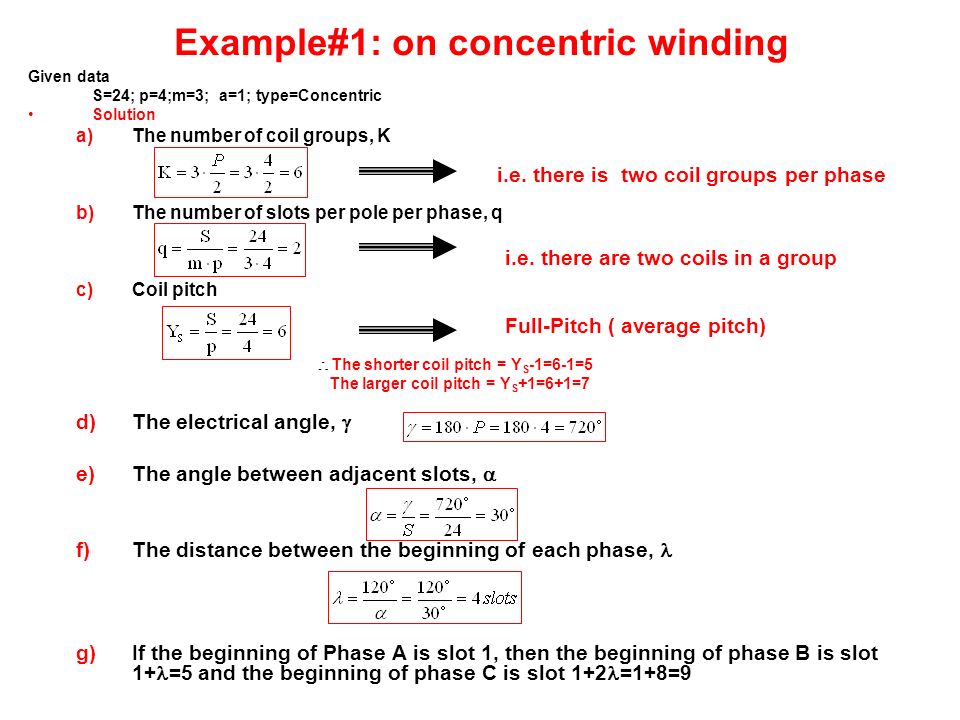
Based on conductor size, number conductors per slot and arrangement of conductors similar to that of stator, dimension of rotor slots can be estimated. Size of the slot must be such that the ratio of depth to width of slot must be between 3 and 4. HPE Server Memory should be installed as indicated based upon the total number of DIMMs being installed per CPU. For example, if two DIMMs are being installed per CPU on a DL385, they should be located in white DIMM slots numbered 16 and 14. If six DIMMs are being used per CPU, they should be installed in DIMM slots 16, 14, 12, 10, 3, and 1. Consider this 3 phase AC machine: It has 36 slots, and 8 poles. (Picture taken from the document: http://www.eecs.ucf.edu/tomwu/course/eel4205/notes/11%20Basic. For a solid or a hollow shaft subject to a twisting moment T, the torsional shearing stress t at a distance r from the centre will be (a) t = Tr/J (b) t = Tr (c) t = TJ/r (d) none of these where J is second moment of area.
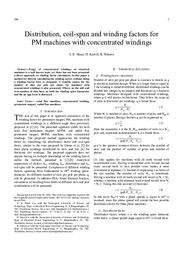
In a concentrated winding, each phase of a coil is concentrated in a single slot. The individual coil voltages induced are in phase with each other. These voltages must be added arithmetically. In order to determine the induced voltage per phase, a given coil voltage is multiplied by the number of series connected coils per phase. In actual practice, in each phase, coils are not concentrated in a single slot. They are distributed in a number of slots in space to form a polar group under each pole.
The voltages induced in coil sides are not in phase, but they differ by an angle β which is known as the angular displacement of the slots. The phasor sum of the individual coil voltages is equal to the total voltage induced in any phase of the coil.
Let,
M = slots per pole per phase
β = angular displacement between adjacent slots in electrical degrees
Thus, one phase of the winding consists of coils arranged in m consecutive slots. Voltages EC1, EC2, EC3….. are the individual coil voltages. Each coil voltage EC will be out of phase with the next coil voltages by the slot pitch β.
The figure below shows the voltage polygon of the induced voltages in the four coils of a group (m = 4)
The voltages EC1, EC2, EC3 and EC4 are represented by the phasors AB, BC, CD and DF respectively. Each of these phasors is a chord of a circle with the center O and subtends an angle β at the point O. The phasor sum AF, represents the resultant winding voltage, subtends at an angle mβ at the center.
The arithmetic sum of the individual coil voltage is given as
The phasor sum of the individual coil voltages is given as
The Number Of Slots Per Pole Should Beams
Therefore, from the equation (1) shown above, we know that,
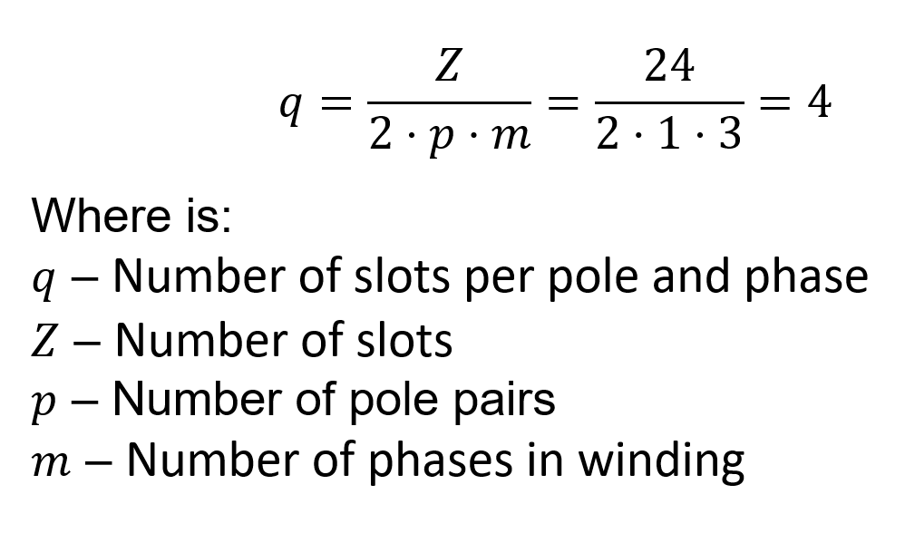
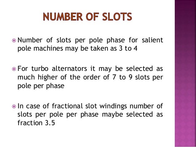
The distribution factor Kd for a given number of phases is dependent only on the number of distributed slots under a given pole. It is independent of the type of the winding, lap or wave or the number of turns per coil, etc. the distribution factor decreases as the number of slots per pole increases.
Related terms:
For A 5 Kw Dc Motor The Number Of Slots Per Pole Should Be


The Distribution Factor or the Breadth Factor is defined as the ratio of the actual voltage obtained to the possible voltage if all the coils of a polar group were concentrated in a single slot. It is denoted by Kd and is given by the equation shown below.
In a concentrated winding, each phase of a coil is concentrated in a single slot. The individual coil voltages induced are in phase with each other. These voltages must be added arithmetically. In order to determine the induced voltage per phase, a given coil voltage is multiplied by the number of series connected coils per phase. In actual practice, in each phase, coils are not concentrated in a single slot. They are distributed in a number of slots in space to form a polar group under each pole.
The voltages induced in coil sides are not in phase, but they differ by an angle β which is known as the angular displacement of the slots. The phasor sum of the individual coil voltages is equal to the total voltage induced in any phase of the coil.

The Number Of Slots Per Pole Should Be Paid
Let,

M = slots per pole per phase
β = angular displacement between adjacent slots in electrical degrees
Thus, one phase of the winding consists of coils arranged in m consecutive slots. Voltages EC1, EC2, EC3….. are the individual coil voltages. Each coil voltage EC will be out of phase with the next coil voltages by the slot pitch β.
The figure below shows the voltage polygon of the induced voltages in the four coils of a group (m = 4)
The voltages EC1, EC2, EC3 and EC4 are represented by the phasors AB, BC, CD and DF respectively. Each of these phasors is a chord of a circle with the center O and subtends an angle β at the point O. The phasor sum AF, represents the resultant winding voltage, subtends at an angle mβ at the center.
The arithmetic sum of the individual coil voltage is given as

The phasor sum of the individual coil voltages is given as
Therefore, from the equation (1) shown above, we know that,
The distribution factor Kd for a given number of phases is dependent only on the number of distributed slots under a given pole. It is independent of the type of the winding, lap or wave or the number of turns per coil, etc. the distribution factor decreases as the number of slots per pole increases.